Advanced
Schematics
The pretty colorful pictures that we have been using so far are not very useful in practical projects. You can’t really draw them by hand, different components may look very similar, and it’s hard to see what is going on when there are a lot of connections. That’s why engineers prefer to use more symbolic representation of connection, a schematic.
A schematic doesn’t care how the parts actually look like, or how their pins are arranged. Instead they use simple symbols. For instance, here’s a schematic of our experiment with the external LED:
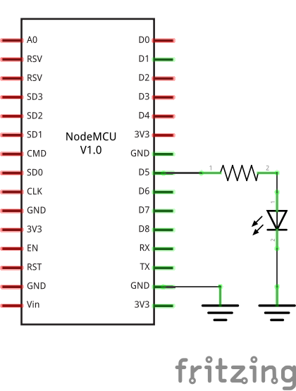
The resistor is symbolized by a zig-zag. The LED is marked by a diode symbol (a triangle with a bar), with additional two arrows showing that it’s a light emitting diode. The board itself doesn’t have a special symbol – instead it’s symbolized by a rectangle with the board’s name written in it.
There is also a symbol for “ground” – the three horizontal lines. Since a lot of components need to be usually connected to the ground, instead of drawing all those wires, it’s easier to simply use that symbol.
Here are some more symbols:
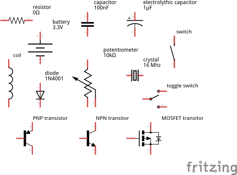
It’s important to learn to read and draw electric schematics, because anything more advanced is going to use them, and you will also need them when asking for help on the Internet.
Analog to Digital Converter
Our board has only one “analog” pin, A0. That pin is connected to an ADC,
or “analog to digital converter” – basically an electronic voltmeter, which
can tell you what voltage is on the pin. The one we have can only measure from
0 to 1V, and would be damaged if it got more than 1V, so we have to be careful.
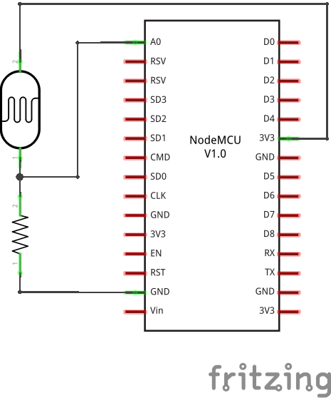
We will connect a photo-resistor to it. It’s a special kind of a resistor that changes its resistance depending on how much light shines on it. But to make this work, we will need a second, fixed, resistor to make a “volatge divider”. This way the voltage will change depending on the resistance of our photo-resistor.
Now, we will just read the values in our program, and print them in a loop:
from machine import ADC
adc = ADC(0)
while True:
    print(adc.read())
You should see a column of numbers changing depending on how much light the photo-resistor has. Try to cover it or point it toward a window or lamp. The values are from 0 for 0V, to 1024 for 1V. Ours will be somewhere in between.
Communication Protocols
So far all devices we connected to the board were relatively simple and only required a single pin. More sophisticated devices are controlled with multiple pins, and often have very elaborate ways in which you have to change the pins to make them do something, like sending a character to them, or retrieving a value. Those ways are often standardized, and already implemented for you, so that you don’t have to care about all the gory details – you just call high-level commands, and the libraries and/or hardware in your board handles it all for you.
Among the most popular protocols are UART, I²C and SPI. We are going to have examples of each of them, but we are not going to get into details of how they work internally. It’s enough to know that they let you send bytes to the device, and receive bytes in response.
Neopixels
Those are actually WS2812B addressable RGB LEDs, but they are commonly known as “neopixels”. You can control individually the brightness and color of each of the LEDs in a string (or matrix, or ring). The connection is simple:
And the code for driving them is not very complex either, because the library for generating the signal is included in Micropython:
form machine import Pin
import neopixel
pixels = neopixel.Neopixel(Pin(14, Pin.OUT), 8)
pixels[0] = (0xff, 0x00, 0x00)
pixels.write()
Where 8 is the number of LEDs in a chain. You can create all sorts of
animations, rainbows and pretty effects with those.
Temperature and Humidity
The DHT11 and DHT22 sensors are quite popular for all sorts of weather stations. They use a single-wire protocol for communication. Micropython on ESP9266 has that covered:
from machine import Pin
import dht
sensor = dht.DHT11(Pin(2))
sensor.measure()
print(sensor.temperature())
print(sensor.humidity())
The connections are simple:

LED Matrix and 7-segment Displays
Adafruit sells a lot of “backpacks” with 7- or 14-segment displays or LED matrices, that we can control easily over I²C. They use a HT16K33 chip, so that we don’t have to switch on and off the individual LEDs – we just tell the chip what to do, and it takes care of the rest.
The schematic for connecting any I²C device will be almost always the same:
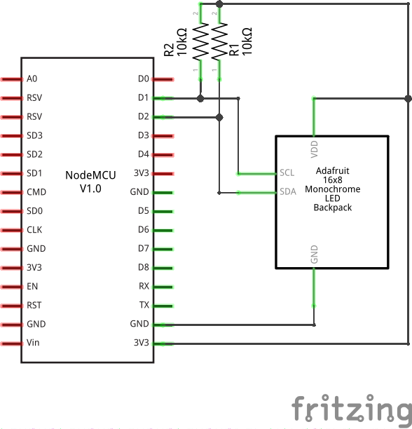
Note
The two resistors on the schematic are needed for the protocol to work reliably with longer wires. For our experiments, it’s enough to rely on the pull-up resistors that are built into the board we are using.
The communication with the backpack is relatively simple, but I wrote two libraries for making it more convenient. For the matrix:
from machine import I2C, Pin
from ht16k33_matrix import Matrix8x8
i2c = I2C(sda=Pin(4), scl=Pin(5))
display = Matrix8x8(i2c)
display.brightness(8)
display.blink_rate(2)
display.fill(True)
display.pixel(0, 0, False)
display.pixel(7, 0, False)
display.pixel(0, 7, False)
display.pixel(7, 7, False)
display.show()
and for the 7- and 14-segment displays:
from machine import I2C, Pin
from ht16k33_seg import Seg7x4
i2c = I2C(sda=Pin(4), scl=Pin(5))
display = Seg7x4(i2c)
display.push("8.0:0.8")
display.show()
TFT LCD Display
The I²C protocol is nice and simple, but not very fast, so it’s only good when you have a few pixels to switch. With larger displays, it’s much better to use SPI, which can be much faster.
Here is an example on how to connect an ILI9340 display:
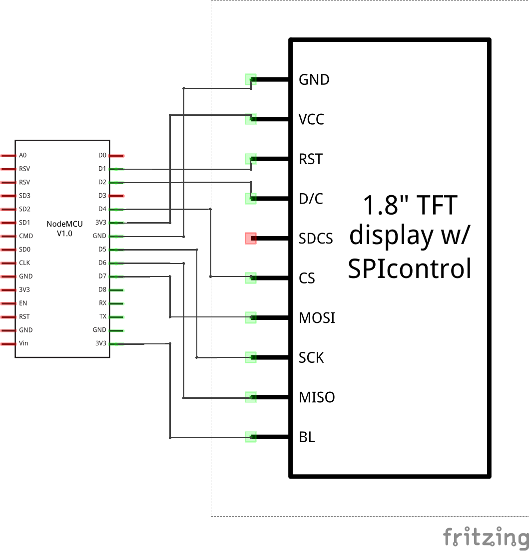
And here is a simple library that lets you draw on that display:
from machine import Pin, SPI
import ili9341
spi = SPI(miso=Pin(12), mosi=Pin(13), sck=Pin(14))
display = ili9341.ILI9341(spi, cs=Pin(2), dc=Pin(4), rst=Pin(5))
display.fill(ili9341.color565(0xff, 0x11, 0x22))
display.pixel(120, 160, 0)
As you can see, the display is still quite slow – there are a lot of bytes to send, and we are using software SPI implementation here. The speed will greatly improve when Micropython adds hardware SPI support.